.png?h=91&la=en&w=194&revision=aebd5769-3561-4624-b59a-0b22767331bc&hash=7CEA00A0C4A0C0E995840DDF1D80BFD1)
.png?h=53&la=en&w=113&revision=6d5ac094-01fa-4dd7-86f7-a6200ba6d962&hash=795C9A6D7BED3F4E33F0E3A437F30009)
Frequently Asked Questions
-
Are IVI Instrument Drivers Compatible with Linux?Discussing the feasibility of using an IVI instrument driver under a Linux OS.
Due to the necessity to have ultimate control over the stability and maintenance of their test system, many users prefer to avoid designing their SW to be dependant on a Windows operating system. The alternative of choice tends to be Linux. For users who wish to use LXI instrumentation, will have this question of whether or not the IVI instrument driver that comes standard with their LXI hardware work in Linux. To understand this, please refer to the following diagram:

First of all, it is important to note that there are two levels of IVI compliance. IVI – COM and IVI-C. Although only one of the two is required for LXI instruments, it is quite common industry wide, to deliver both with LXI instruments. Part of the reason for this is industry tools commonly used to develop IVI drivers generate an IVI-COM driver at the core, and automatically wrap the IVI-COM driver with an IVI-C driver, thus creating both deliverables. This model ultimately poses problems for Linux users
COM in general is a Microsoft technology, and is an architecture that is heavily dependent on characteristics specific to the Windows operating system. So, as a rule of thumb, IVI-COM driver will not work on a Linux OS.
If we continue with the diagram above, IVI-C will not work under Linux either due to the fact that the IVI-C driver is dependent on the IVI-COM driver. In theory, a pure IVI-C driver could work under Linux, but there is one thing that is worthy of considering. IVI-C instrument drivers require some kind of VISA drivers to be functional. While there are some Linux based VISA libraries available in the industry, they are limited in functionality, and support. While this approach is possible, it is challenging.
VTI Instruments is committed to providing it’s customer base with an open software architecture. What this means is we strive to allow our customers to develop in the OS and ADE of their choice. When considering this problem upon designing the first LXI instrument, it was necessary to find a way to deliver an IVI driver as well as a system that was easily integrated onto a Linux OS.
The solution involved creating a core driver that contained all of the functionality to control the device. This is illustrated in the diagram above. The higher level IVI-COM and IVI-C drivers are nothing more than wrappers to the true VTI Instrument core driver. The advantage to this approach is the core driver can be delivered to customers who prefer Linux to Windows. While they don’t get an IVI compliant driver, they do get a driver that delivers the same exact functionality without any of the caveats introduced by IVI to Linux users. -
Can I Use Two DACs in Series to Increase Output Voltage?In many applications, the maximum output voltage of one DAC is not sufficient to meet the requirements of the specific test. In these cases, when wired correctly, two DACs can be used together to increase the total output voltage. You can increase the specified output voltage in a system by utilizing two or more isolated DAC channels from one or more output devices wired in series. Isolated DAC outputs can be found on the EX1200-3604/3608 card as well as the VM3618. Make sure to check the "Maximum output (series channels)" or the "Isolation" in the product specification, as there is a limit to the output voltage that can be achieved in this way. Also, make sure that the output channels are isolated. For example, the VM3608/VM3616 are NOT isolated and may not be used in series.
Because the output is unipolar, we will reference our voltages to the RETURN signal pins. The example below shows how to wire two channels together to increase the output range from 0-32V to 0-64V.

-
Control Hardware (Stimulus) – Analog OutputThe control hardware performs an opposite task from the measurement hardware, interpreting digital words (commands) from the computer and outputting the appropriate electrical signals (voltages, currents, pulses, waveforms). These signals control fans, motors, valves, and heaters or route power and signals to external devices. Control hardware can be used for three types of control: analog output, digital output, and switching. Analog Output The D/A converter performs the opposite function of an A/D converter. It interprets commands from the computer and outputs the proper dc voltage or current. The output stays at this output level until the computer tells the D/A converter to output a new value. The voltage or current from the D/A converter can be used to control the speed of a fan, the position of a valve, or the flow rate of a pump. D/A converters are used in applications that require precise control of external devices. One specialized type of D/A converter is the arbitrary waveform generator.
This device contains memory and a clock and can output a series of dc voltages at varying rates. The memory is used to store these voltage values and the clock determines the output rate. When the clock rate is fast enough, these dc voltages or waveforms take shape of sine, square, or ramps output.


VTI Instruments offers a wide variety of analog control hardware in both the LXI and VXI form factors. -
Control Hardware (Stimulus) – Digital OutputThe control hardware performs an opposite task from the measurement hardware, interpreting digital words (commands) from the computer and outputting the appropriate electrical signals (voltages, currents, pulses, waveforms). These signals control fans, motors, valves, and heaters or route power and signals to external devices. Control hardware can be used for three types of control: analog output, digital output, and switching.
The digital output card interprets a command from the computer and outputs a high or low voltage on each of its channels (bits). It is commonly used to turn on/off small lights or to send digital words to machinery. The pulse output card is a combination of a digital output card and an arbitrary waveform generator. Like the waveform generator, it contains a clock. It outputs a series of pulses at varying rates. The most common use of a pulse output card is to control stepper motors. That is the reason this card is sometimes called a stepper motor controller. Stepper motors are used in applications to move an object. These motors vary in size from miniature to large overhead cranes. The number of pulses determines the distance traveled while the frequency of the pulses is the speed at which this distance is traversed. Sophisticated stepper motor controllers can be programmed to accelerate and decelerate the motors.

-
Do I Need a Crossover Cable for LXI Instrumentation?
LXI specification mandates the implementation of Auto-MDIX on the Ethernet interface to every LXI device. What this means for users is that they need not worry about whether the CAT-5 cable they use is “crossover” or “straight through.” The Ethernet interface of the LXI device will automatically resolve these details internally. -
Does LXI Support Gigabit Ethernet?
The short answer is, Yes.
LXI standard uses Ethernet as its communication protocol. Vendors, at their option, are free to implement the 10/100 or Gigabit version of Ethernet, based on data transfer speeds needed. The LXI consortium has made backwards compatibility a requirement with respect to network performance. Hence, 10/100 Ethernet based LXI instruments, as well as, Gigabit Ethernet based LXI instruments can all be put on the same network, and operate without any problems.
Refer to data sheet of specific LXI instrument for more information on its Ethernet version. -
How Can I Decrease Test Time in High Channel Count Switch & Measure Applications?In the area of functional test, often test time is a critical requirement. Latency in commanding signal switch paths, stimulus devices, and the measurement can have a significant impact on the overall time it takes to complete a full functional test of a particular DUT.
Using the VXI bus in combination with the VM2710 DMM and SMIP family of switching products, scanlists can be used to greatly reduce the latency introduced by using the host PC to control switch closures. Specifically, the user can pre-load the SMIP switches with a list of relays, or channels that are to be measured by the DMM. After that, hardware triggers are used instead of the host PC to control the sequencing of events. The process is as follows:
DMM Setup (1 Communication Transaction From PC)
Trigger System Setup (1 Communication Transaction From PC)
Load Scanlist (1 Communication Transaction From PC)
Initiate Scan (1 Communication Transaction From PC)
From here, the HW repeats the following routine
Switch Closure. Once Settled Trigger is Sent to the DMM
DMM takes a measurement. Once Completed a Trigger is Sent to the Switch
Repeat….
The time saved with this approach is directly related to the number of channels that need to be measured. For example, if a total of 500 channels need to be measured, a well planned routine can turn 504 communication transactions from the PC into only 4, and thus greatly improving the time the test takes to complete.
The EX1200 is also a scanning DMM platform w/signal switching. This particular product exemplifies how this same concept can be taken one step further to completely optimize test times. In addition to being able to include switch closures in the scan list, this platform provides an interface to include DMM and stimulus setup as part of the scan. For tests that require multiple measurement functions out of the DMM, this is a valuable feature. The process would be as follows:
Load Scanlist (1 Communication Transaction)
Initiate Scan (1 Communication Transaction)
From here, the HW repeats the following routine
Switch Closure. Once Settled Trigger is Sent to the DMM
DMM takes a measurement. Once Completed a Trigger is Sent to the Switch
Repeat….
DMM Receives a Separate Trigger Instructing it to Change Measurement Function. Once Completed a Trigger is Sent to the Switches
Switch Closure. Once Settled Trigger is Sent to the DMM
DMM takes a measurement. Once Completed a Trigger is Sent to the Switch
Repeat….
Now, a test consisting of thousands of channels and many different measurement types can be completed in the most efficient amount of time as possible, and virtually independent of a host PC. -
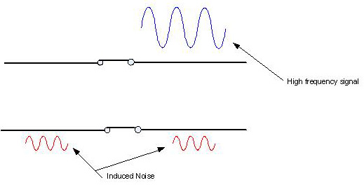
What is AC Isolation with Respect to Signal Switching?Switches are designed to distribute a signal. However, in doing so, they will distort the signal to some extent. This distortion should be well defined and quantified in the switch specification. This information allows users to accurately choose a switch that is appropriate given the needs of their application.
High frequency signals can sometimes couple across an open relay. The quantification of a switches ability to reject this undesired phenomenon is called isolation and is specified in dB to express the magnitude of the coupled signal. The greater this number, the better the isolation.

Isolation will typically be expressed from input to output of the worst case channel, with the relay open. The isolation specification is important to consider since it determines the amount of noise that is induced to the output of a channel from the input of that channel when the channel is open. -
What is an A/D Converter?The A/D converter, a key element in a DAC system, is used to convert dc voltages from transducers into digital words (data). The voltage represents a temperature, pressure, flow, pH, or speed and must be converted to a digital word before it can be passed to an intelligent device like a computer.
A voltmeter performs the same task as an A/D converter. A multi-meter is a superset of a voltmeter and A/D converter. In addition to measuring dc voltages, the multi-meter can measure ac voltage, resistance, and sometimes current. The A/D converter is specified in bits.
The number of bits defines the resolution, the smallest voltage change that the A/D converter can distinguish. If an A/D converter is 8 bits, it can distinguish up to 28 or 256 parts. If the A/D has a range of (0 - 10) V, it can sense changes in steps of 10/256 = 0.0391 V. Voltmeters are usually specified in digits.

-
What is Common Mode Noise?Common mode noise is electrical interference on the two signal lines that causes both lines to change in potential relative to ground. Common mode noise most often results when the ground potential between the measuring instrument and the device being measured are different. The difference in grounds results in a ground loop, a current flowing through ground and the low lead. Once this current appears in the low lead wire it will cause a voltage because the wire has some resistance. The longer the lead, the more lead resistance and the greater the voltage error.
TIP: To reduce common mode noise, use a guarded voltmeter. Tie the guard to the low side of the device being measured. This will shunt any ground loop currents away from the high and low measurement wires.

-
What is Digital Noise?Sometimes digital circuitry on measurement devices can affect the analog front end of the device. Digital circuitry passes information in the form of voltages, switching from high to low at high speeds. This activity creates high frequency noise that can easily be transferred to analog signals that come in close proximity.
TIP: Never allow sensitive signals to pass near digital circuitry like that found in a computer. (Cards plugged into a PC may be susceptible to digital noise present in the computer). -
What is LXI?
LXI Overview
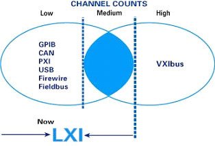
The functional test and data acquisition community has been instrumental in establishing many industry standards, ranging from communications interfaces to instrumentation backplanes. The need for ever increasing bandwidths and higher data transfer rates has helped drive the latest industry initiative, LAN eXtensions for Instrumentation (LXI).
LXI is a powerful test instrumentation platform supported by the world’s leading instrumentation companies. The LXI Consortium was formed in the fall of 2004 by VTI Instruments (formerly known as VXI Technology) and Agilent Technologies. Membership of LXI Consortium has since grown to over 40 leading test and measurement companies from around the globe.
LXI Features
LXI combines the synchronization and triggering features inherent in VXIbus and IEEE-1588 devices, with the benefits of Ethernet and GPIB technologies. The standard defines a platform for small to medium channel density and distributed modular instruments using low-cost, open-standard LAN (Ethernet) as the system backbone. LXI was developed to offer the size and integration advantages of modular instruments without the cost constraints of card-cage architectures. The standard continues to evolve, leveraging current and future LAN functionality, far exceeding legacy T&M connectivity capabilities.
Key attributes that set LXI apart from other architectures are:- Speed, simplicity, worldwide reach, low implementation cost, and backward compatibility of LAN.
- Quick, easy configuration through the intuitive web interface built into compliant instruments.
- Simplified programming and greater software reuse through IVI drivers.
- The ability to create hybrid systems that include LXI, GPIB, VXI and now PXIe.
- Enhanced system performance and event handling via hardware- and LAN-based triggering modes.
- Synchronization of local and remote instruments through the IEEE-1588 precision time protocol.
The LXI Standard Specification can be downloaded from the official website - http://www.lxistandard.org -
What is Maximum Carry Current with Respect to Signal Switching?
Maximum carry current is the amount of current that can safely pass after closing or prior to opening the contacts. This is specification is differentiated from the switching voltage and current tolerances, and is only valid when the relay is closed, and settled.
-
What is OXCO?
In general, the accuracy of an oscillator is specified in parts per million. This means a given oscillator will be off so many parts per each million of its oscillations or “ticks”. Taking the VXI world as an example, the requirement is that each slot-0 controller be capable of delivering a 10MHz reference that is off by no more than 100PPM. This means that to be compliant with the VXI specification, a slot-0 controller must deliver 10 million oscillations +/-1000 ticks every second. Any more error would be non-compliance.
OCXO is a crystal used to deliver superior clock precision and accuracy. Specifically, an oven controlled crystal oscillator is guaranteed to operate at 0.1PPM. In simplest terms, it works by regulating the ambient temperature surrounding the crystal, keeping it at a constant and known level. Temperature is a key parameter which affects the accuracy of a clock.
For those applications which require superior clock performance, VTI Instruments provides OCXO as an option. The VM2164 is a VXI based counter timer device which can be upgraded to use an onboard OCXO oscillator. The EX2500A, a VXI slot-0 controller, typically delivers the standard VXI 10MHz reference with an error of 50PPM, but can be optionally equipped to utilize oven controlled crystal oscillator which delivers 10MHz at 10PPM.
-
What is Path Resistance with Respect to Signal Switching
In signal switching solutions, this specification quantifies the worst case path resistance of a particular switch card from end to end. Specifically, this resistance includes contact resistance introduced by the front panel connectors, trace resistance introduced by the PCB, and contact resistance introduced by the relay itself.
-
What is Task Scheduling in Data Acquisition
The scheduler is a component in data acquisition software that coordinates all other activities, such as sending commands to the instrumentation, as well as the collecting, storing, displaying, analyzing, and printing of data from the instruments. The scheduler ensures that data is collected at prescribed times and at prescribed rates. In menu-driven software, the user fills out menus to define tasks. These tasks consist of the channels to be scanned, measurement type to be made, rate at which measurements are to be made, and the duration of the tasks. The scheduler controls the timing of commands being sent to the measurement hardware (CONTROL) with data being returned to the computer (COLLECTION).
-
What is TCXO?In general, the accuracy of an oscillator is specified in parts per million. This means a given oscillator will be off so many parts per each million of its oscillations or “ticks”. Taking the VXI world as an example, the requirement is that each slot-0 controller be capable of delivering a 10MHz reference that is off by no more than 100PPM. This means that to be compliant with the VXI specification, a slot-0 controller must deliver 10 million oscillations +/-1000 ticks every second. Any more error would be non-compliance.
TCXO is a crystal used to deliver superior clock precision and accuracy. Specifically, a temperature controlled crystal oscillator is guaranteed to operate at 10PPM. In simplest terms, it works by using a feedback loop to adjust the oscillator output based on ambient temperature. Temperature is a key parameter which affects the accuracy of a clock.
For those applications which require superior clock performance, VTI Instruments provides TCXO as an option on several products. The VM2164 is a VXI based counter timer device which can be upgraded to use an onboard TCXO oscillator. The EX2500A, a VXI slot-0 controller, typically delivers the standard VXI 10MHz reference with an error of 50PPM, but can be optionally equipped to utilize temperature controlled crystal oscillator which delivers 10MHz at 10PPM. -
What is the HDLC Serial Protocol?
HDLC is an acronym for "High-Level Data Link Control". It is adopted from the de facto standard SDLC (see below). HDLC is a message based protocol used for serial communications. HDLC implements a "start flag" and "stop flag" that is a specific sequence of bits (0x7E7E, or 0111 1110 0111 1110) that results in a unique pattern that can be detected by the receiving device. This pattern is used to identify the beginning or end of an incoming message. In order to prevent conflicts with actual data in the sequence that might appear as a start or stop flag, the HDLC protocol uses a "bit stuffing" scheme called "Zero-bit insertion" in any part of the data stream that is a part of the message.
This bit stuffing scheme will always insert a 0 following any 5 "1's" bits in a message sequence, whether or not the next bit in the sequence is a 1. This way the receiver will always know that following 5 1 bits the next bit should be a zero if it is part of a message, and will automatically dispose of this extra 0 bit. If there are 6 1's in sequence, it will indicate either the start or end of a message. The VM6068 is a VXI based serial I/O device which supports the HDLC serial protocol. -
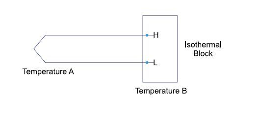
What is Thermal Noise?When two dissimilar metals are joined together and the temperatures between the two ends are different, a potential (voltage) will be present across the two leads. Any connections of dissimilar metals in your system can create the same effect. Extra consideration should be taken wherever there is metal to metal contact within a data acquisition system.
TIP: Do NOT connect thermocouple wire directly to the voltmeter. Thermocouples require an isothermal temperature block so that both leads are at the same temperature and the thermocouple effect between the wires and the terminals is negated.
Transducers like RTDs, thermistors, and strain gages are devices whose output resistance changes. All require power to make them work. When power is applied to a resistive device, it heats up. The rise in temperature causes a change in resistance and an error in the measurement.
TIP: To eliminate self-heating effects, do not apply power to the device any longer than necessary.
TIP: For best results, make two measurements, one without power applied to the transducer and one with power applied. Simple subtraction will eliminate the thermal noise.
-
What is VISA?
VISA (Virtual Instrument Software Architecture) is an industry specification for communicating to test and measurement devices with respect to software regardless of the hardware interface. Specifically, VISA standardized on data types and a number of communication protocols in order to deliver a common platform to vendors for developing instrument drivers. For end users, the result is a transparent interface to communicate with test and measurement devices regardless of the hardware interface. The following illustration serves as a visual example with respect to the VXI platform:
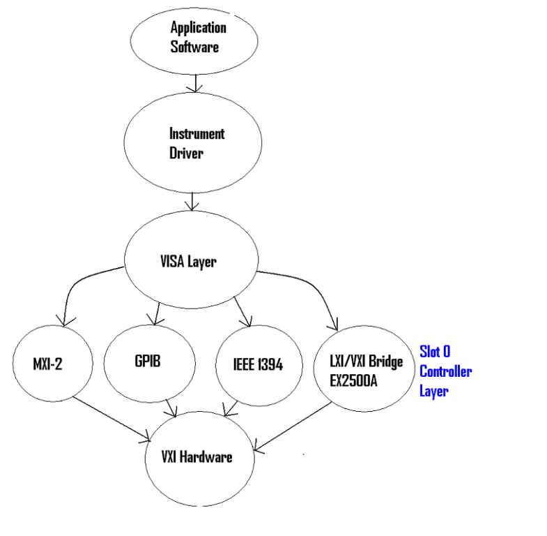
Sticking with the VXI example, the benefit of this for end users is the ability to interchange slot 0 controllers without any modifications to their application SW. For example, it is possible to make a somewhat obsolete VXI system using a GPIB controller completely up to date and current by replacing the GPIB interface with an EX2500A LXI slot zero controller. This update to an Ethernet interface would require no additional SW development and would extend the longevity of the system for many years to come.
There are two primary developers of the VISA libraries. Specifically, National Instruments, and Agilent Technologies have separate implementations of the VISA libraries. Users can install one or both of these library sets depending on what hardware is being used in their test system. For installing the EX2500A, users should use Agilent I/O Libraries Suite 15.0 or later.
-
Why won't my EX2500A Slot Zero Controller work with ZTEC Instrument's ZT412VXI Oscilloscope?
This is a timing issue between the two devices. You will have to contact the technical support department at ZTEC for an update to the oscilloscope's DSP. -
Why won't my EX2500A slot zero controller work with ZTEC Instruments' ZT532VXI Signal Generator?
This is a timing issue between the two devices. You will have to contact the technical support department at ZTEC Instruments to get an update to the DSP on the signal generator. -
How Can Scanning Architectures Affect Measurement Accuracy?
With respect to data acquisition systems, measurement devices can be either scanning or parallel architectures. Parallel architectures utilize an independent analog to digital converter on a per channel basis while scanning architectures typically use a multiplexer to scan each channel to one analog to digital converters.
Parallel architectures are generally preferred as they provide superior accuracy and better synchronization when compared to a scanning system. However, they are also more expensive, and are only justified in those applications that require a higher level of accuracy
The phenomenon that introduces inaccuracies in a multiplexed data acquisition system is commonly referred to as “channel bleeding.” Specifically, when a measurement on one channel affects the accuracy of the measurement on the following channel in the system. For example, consider the case where a very large voltage measurement is immediately followed by a low voltage measurement on the same ADC. In this case, if the scan rate is too fast, the ADC may not have a chance to dissipate the large voltage before taking the smaller voltage reading. The result is inaccuracies in the smaller voltage measurement. Another scenario to consider is when a valid temperature channel is followed by an open transducer (damaged thermocouple) condition. The front end of the instrument, being high impedance, will only slowly drift. Again, if the scan rate is too fast, this measurement will appear to be very close to the proceeding channel, and will appear valid even though in reality, the transducer is faulty.
There are strategies to mitigate the effects of this phenomenon. The EX10XXA family of products utilize a scanning architecture to take both temperature and voltage measurements. Despite the scanning nature of this system, this device is known for it’s high level of accuracy in delivering temperature and voltage measurements.
In addition to analog and programmable, digital filtering, this product is designed with independent channel to channel signal conditioning which goes a long way to prevent against channel bleeding effects. Specifically, independent gain stages on each channel allow some channels to measure large voltages with respect to adjacent channels with no negative effects on the measured data.
Furthermore, each channel can independently source a very small amount of current to the transducer. This source will have negligible effect on the accuracy of the measurement, but in the case of an open transducer, the current will quickly drive the measurement amplifier into saturation, creating a reliable and indicative overload condition.
Users receive a low cost solution that delivers many of the same advantages in terms of accuracy as a parallel implementation. -
How Do I Configure My LXI Device with a Static IP Address?
As per LXI standard, all instrument vendors must implement an embedded web page which allows users to configure LAN parameters. This web page allows you to select Static IP configuration option, if needed. The following is an example of such an interface, and should look very similar from device to device regardless of vendor.
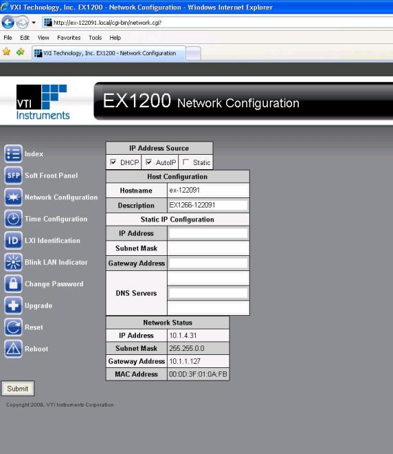
Usually, all LXI instruments offer DHCP, AutoIP and Static (also called as Manual) options for configuring the LAN. However, if more than one option is enabled, the LXI Device‘s LAN configuration will proceed in the above order.
Note: AutoIP is also referred as Automatic Private IP Addressing (APIPA), and Dynamically Configured Link Local Addressing. -
How Do I Determine the Automatic IP Address of My LXI Device?
Auto IP is also commonly referred as Automatic Private IP Addressing (APIPA), and, Dynamically Configured Link Local Addressing.
This is a mechanism for finding an unused IP address in the range 169.254.X.Y, where X is in the range 1 through 254 and Y is in the range 0 through 255. The device will first attempt to obtain the specific address 169.254.X.Y, where X and Y are the second-to-last and last octets (bytes) of the device’s MAC address. However, X will be set to 1 if it is 0 in the MAC address, and to 254 if it is 255 in the MAC address. This is in accordance with the Auto IP standard (RFC 3927). If this address is already in use, the unit will attempt to obtain other IP addresses in a pseudorandom fashion until it finds one that is available.
To illustrate the Auto IP mechanism, the following table lists the Auto IP default address for some example MAC addresses.
MAC Address IP Address 00:0D:3F:01:00:01 169.254.1.1 00:0D:3F:01:01:01 169.254.1.1 00:0D:3F:01:A3:28 169.254.163.40 00:0D:3F:01:FE:FE 169.254.254.254 00:0D:3F:01:FF:FE 169.254.254.254
Usually the addresses that were obtained using AutoIP are not guaranteed to be unique, beyond a single network segment.
If this strategy does not work for successfully, see the knowledge base entry for resetting the LAN settings on the device, and configure parameters per your needs.
-
How Do I Reset the Network Settings on My LXI Device?
In some cases, it may become appropriate to reset the network settings on an LXI device. For example, if a colleague has used the device, configured it with a static IP address, and no longer remembers that IP address, than there is no way to access the box until it is brought back to a known state. LXI Standard defines the LAN Configuration Initialize (LCI) mechanism, which when activated, places its network settings in a default state.
The default state of all LXI devices manufactured by VTI Instruments is Auto-IP mode with DCHP service enabled. To get the device back to this state:
Locate the recessed "Reset" button on the back panel of the device
With the device turned off, push and hold the Reset Button
Continuing to hold the button, and power on the device
Wait for 1 minute, and release the Reset button
Wait 1 minute for the device to reboot
At this point, all the default network settings should take affect. -
How Do I Uniquely Identify LXI Devices?
Regardless of the platform, a necessary requirement of automated test equipment is the ability to be able to uniquely identify and reference each instrument independently. Considering legacy platforms, in VME, it is necessary to pre-assign a portion of address space for each device in the system. With VXI, users must assign a unique logical address to each device in the system. LXI comes with the same basic requirement. A natural choice for serving this purpose is using the device’s IP address to uniquely identify each instrument on the network.
For further details on configuring the network settings of LXI devices, see knowledge base entries on
Auto-IP
Static IP
DHCP
LXI Instrument Discovery -
How Often Should I Calibrate My Instruments?
As a rule of thumb, factory level calibration is usually performed once a year. With that said, it is important to also consider the application at hand, and the amount of accuracy that is required with respect to the hardware specifications. Generally, the longer it has been since a factory calibration, the more an instrument’s accuracy will drift from the published tolerances. In some cases, vendors will specify additional errors based on time drift and temperature drift from the last factory calibration.
In order to eliminate errors due to thermal drifts in between factory calibrations, some instruments provide the capability to perform a self-calibration. Specifically, the instruments are equipped with a known precision voltage source which can be routed through the measurement path. Taking the known voltage and comparing it with the measured voltage allows for automatic, minor adjustments. This provides for accurate and reliable measurements in between factory calibrations.
Look for this self calibration capability on all VTI Instrument’s LXI data acquisition devices including the EX10xxA family of products, the EX1629 strain measurement device and the EMX family of products. -
How To Connect to and Control LXI DevicesSoftware Installation
Host PC Requirements
Windows 8/7/XP Operating System.
Internet Explorer or Google Chrome or Firefox Mozilla.
Additional Required Software
LXI Discovery Tool.
Java Runtime Environment Latest Version.Both LXI Discovery Tool and Java Runtime Environment are free to use software. They can be downloaded from https://www.lxistandard.org/Resources/LXIDiscoveryTool.aspx & https://www.java.com/en/download/ respectively.
2. Install the Instrument
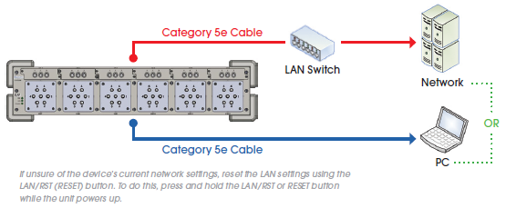
Connect Instrument Host PC/LAN
Requires Category 5e/ Category 6 Ethernet cable.
If connecting to a LAN, a 10/100/1000 switch will be required as well.
Connect the power cord to the LXI instrument and power on the device.
Wait for the LAN LED to turn green. The device is now ready to be discovered.
3. Discover the Instrument
Open LXI Discovery Tool Software
Open LXI Discovery Tool and click on Search Tab.
Select the instrument and click on the Open Web Page Tab.
.jpg?revision=f48edb2a-7b2e-4873-a2a3-3290a9a360c5&la=en&hash=5E50CBF214CD2582A6C74A95B34A3BCF)
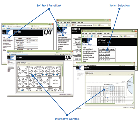
4. Use the Embedded Web Page
Configure the Instrument
Set network and time configuration, define a password, configure channel settings, and control the instrument over Ethernet.
Access Soft Front Panel
If available, click on the Soft Front Panel link in the command menu.
Close relays, connect ports, set and/or change values information using the interactive controls.
-
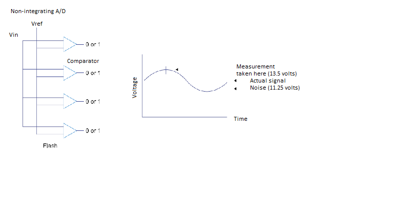
Integrating vs. Non-Integrating A/D ConvertersThere are two types of A/D converters - integrating and non-integrating.
Non-Integrating A/D
The non-integrating Flash converter compares the input voltage (Vin) to a set of known (reference) voltages (comparator). A digital value (0 or 1) is assigned based on the results. If any noise is present on the signal at the time it is digitized, the digital word will reflect that error. Flash converters tend to be expensive because of the cost of accurate voltage references.
Another type of non-integrating A/D, the successive approximation A/D, is less expensive than a Flash converter. It uses one comparator and generates reference voltages, comparing each one to the input signal. If the input signal is varying, a voltage error can occur.
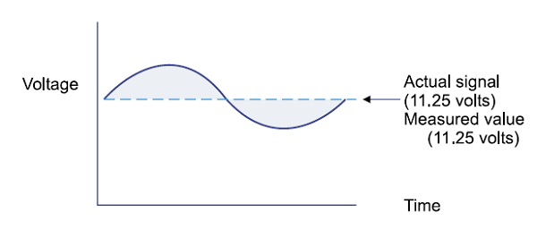
Integrating A/D
The integrating A/D converter integrates the input signal over a period of time. Over that time period, the noise on the input signal is integrated to zero, leaving the actual signal value. Most noise is related to power lines and exists at 60 Hz in the U.S. and Canada and at 50 Hz in Europe and other parts of the world.
A digital input card is used to determine whether an external device is on or off by sensing the presence or absence of a voltage. In the DAC system, the computer can interrogate the digital card to determine which channels contain a high/low voltage. The digital input can only report ON/OFF status and not the value of the voltage on each channel (sometimes called a bit). The bit is considered to be ON if the voltage exceeds a certain value. Digital cards are usually 8, 16, or 32 channels. They can monitor a number of devices. For example, a digital card can be attached to a simple operator panel to sense the position of switches on that panel. In other cases, a digital input card can be connected to machinery (like a dynomometer) that outputs its status in the form of digital words (8 bits).
-
Methods for Data Recording and Storage in Data Acquisition
Data returned to the computer can be stored, displayed, or analyzed. In most cases, the data is collected and stored in memory or on disk. When large amounts of data are collected, database software may be used. Depending on sophistication, the software can scale and convert the data returning from the measurement hardware before it is stored. Intelligent card cage products perform these functions in the instrument, freeing the computer for analysis and display.
In memory intensive applications, one strategy commonly used is to convert the collected data into binary format. This allows users to store the same information that might be conveyed by floating point numbers in a smaller footprint
EXLab is a powerful data acquisition software package made available by VTI Instruments that allows users to connect and control data acquisition hardware, view and record data test sets, as well as, perform analysis and exportation on data. This software package exemplifies some of the common practices in data storage. Specifically, users have a wide variety of options when deciding how they would like to store collected test data. In addition to storing the data locally on the hard disk of the host PC, for higher data throughput applications, users can take advantage of a VXI or PXI based throughput disk. The VT2216 is a VXI based hard disk that takes advantage of the local bus on the VXI backplane to stream data directly from VXI data acquisition hardware to this embedded hard drive. The EMX-2401 is a PXIe embedded controller with a hard drive that allows to stream data directly from PXIe data acquisition hardware to the embedded hard drive through the PCIe backplane. -
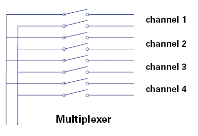
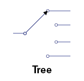
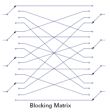
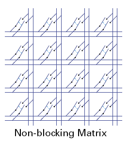
Understanding Different Switching Configurations
A typical automated switching system consists of several switch cards and switch configurations combined together to achieve some desired result. The flexibility, modularity and other requirements play an important role in selecting the correct switching components for a particular application. Care needs to be applied to how these building blocks are used and combined since the size, cost, versatility, and signal integrity can vary widely. The main types of switch configurations are tree, multiplexer, and matrix.
The tree configuration only allows one channel to be selected at a time, whereas the multiplexer can allow all channels to be selected simultaneously. The multiplexer configuration, however, has limited bandwidths due to un-terminated stubs hanging onto the selected channel. The tree configuration is typically used in RF applications, whereas the multiplexer is used for general purpose switching.
The matrix is the most flexible type of switch topology, since any input can be connected to any output. However, it is also the most expensive, and effects overall signal integrity more than other configurations.
A low frequency matrix has large un-terminated stubs, whereas a matrix designed for RF applications has no un-terminated stub effects. Although the matrix is the easiest topology to specify for a complete switching solution, it is best to break the switch solution into smaller building blocks that consist of each of the switching topologies described. This will considerably improve the size, cost and integrity of the overall solution.
-
Understanding Reference Oscillator Specifications.
In general, the accuracy of an oscillator is specified in parts per million. This means a given oscillator will be off by up to so many ticks per each million oscillations. Using the VXI platform as an example, the standard specification requires that each slot zero controller be capable of delivering a 10MHz reference that is off by no more than 100PPM. This means that to be compliant with the VXI specification, a slot zero controller must deliver 10 million oscillations +/-1000 ticks every second. Any more error would be non-compliance.
Some devices put a great deal of importance on the accuracy of their reference oscillator. The VXI-based VM2164 and the LXI-based EX1200-1538 are examples. These instruments are a precision counter timer that is capable of the following measurement functions:
Period
Pulse Width
Rise/Fall Time
Burst/Pulse Characterization
Frequency
In this case, time becomes a critical point of reference in deriving the various accuracies for the measurement functions. It is for this reason that the device comes with several options for improving the accuracy of the clock, as well as with a feature that allows you to bring in a clock reference from the outside world. These together give the user an appropriate amount of flexibility when determining the required accuracy for their counter timer measurements, and the most appropriate set of hardware. -
What Effect Does Transducer Lead Wire Have on My Measurement?
Introduction: An overview of the effects long lead wires can have on the accuracy of a measurement and some strategies for reducing lead wire lengths as well as an approach to completely mitigating the effects of lead wires
Long lead wires ultimately introduce path resistance into your measurements. More lead wire introduces more resistance, and thus more error in the resulting measurement. Furthermore, lead wires could potentially act as large antennas picking up noise in the surrounding test environment.
LXI (LAN Extensions for Instrumentation) devices introduce a solution to this problem. VTI Instruments LXI devices are capable of being synchronized over large distances due to IEEE 1588 technology. Specifically, this technology allows instruments to synchronize with respect to time over Ethernet. This benefits users by allowing them to distribute their test instrumentation around the DUT thus reducing lead wire lengths, and ultimately improving the accuracy of their measurements. In addition to this, users also benefit financially. Less lead wire equates to fewer materials, and a lower total cost to run tests.
Another approach to solve this problem is to design devices which are capable of adjusting out the effects lead wire resistance. The EX1629 Strain Measurement device comes with 2 A/Ds for each of it’s 48 channels. One A/D is used for the measurement, and the other can be configured to monitor the current across the lead wires. The current in combination with the transducer voltage measurement can be used to calculate the resistance in real time. The device then automatically adjusts the measurement to compensate for lead wire resistance. -
What is a Counter Timer Device?
The COUNTER card can be used to sense the presence or absence of a voltage, much like digital input card. The counter is used to count the number of electronic pulses (totalize), the duration of the pulse (pulse width), or the rate of pulses (frequency) coming out of an external device. Counters may come with a terminal block or, if they measure frequencies above 1 MHz, they may come with BNC connectors. Totalize is a common function used in production applications to sense the number of items being tested or produced. When an item breaks the beam of an optical sensor, its output voltage changes and the counter records the event as another count.
Frequency measurements are common measurements made on flow and RPM transducers. These transducers output a series of pulses proportional to the rate of movement. The counter records the number of pulses (counts) per unit of time (gate). Frequency is the count divided by the gate time.
If the frequency is quite low, a reciprocal counter is used to make a period measurement. In a period measurement, the counter records the amount of time from one pulse to the next. The frequency can be obtained by taking the inverse of the period.
Pulse width measurements are used to determine the length of time a pulse stays at a high (or low) voltage level. One practical application is to use a sensor and measure the amount of time it takes an object to pass this sensor. This measurement can be used to determine the speed of a known object or, if speed is known, the length of an object where size is not known. Time interval measurements can be made by the more sophisticated counters. These measurements are the time between one edge of a pulse and another. If the edges are both the same, the time interval is the period. If one edge is rising and the other is falling, the time interval is equal to the pulse width.
Gated totalize is a special case where two counter channels are used. A count is taken on the A channel only when the B channel has a high or low voltage. Otherwise, the pulses entering on the A channel are ignored.
The VM2164, a VXI based, and the EX1200-1538, a LXI based, counter/timer device are capable of performing all these functions. -
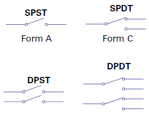
What are Form A, B, and C Relay Types?
An SPST relay (Single Pole Single Throw) simply opens or closes a signal path. This relay is typically normally open when power is removed, and the relay needs to be energized in order to connect the signal path. A normally open relay is some times referred as a Form-A relay
A normally closed SPST relay (i.e., a relay whose signal path is closed when no power is applied) is referred to as Form-B relay.
A DPST relay (Double pole Single Throw) is in essence two SPST relays but energized from the same coil.
A SPDT (Single Pole Double Throw) relay has one normally open and one normally closed path and a DPDT (Double Pole Double Throw) relay is in essence two SPDT relays which are energized from the same coil. A SPDT relay is also referred as a Form C relay.
-
What Are LXI Timed Alarms?
Timed alarms are the capability of an LXI instrument to schedule and perform a particular function at a specific time in the future.
The LXI Instruments, with IEEE-1588 extensions, have a sense of time, using their onboard synchronized clock. Part of the LXI specification is intended to standardize on how instrumentation that uses Ethernet as the primary interface will use this technology to coordinate instruments, and in some cases, optimize test times
One useful application of LXI timed alarms is the ability to coordinate instruments to perform tasks at scheduled times in the future. One specific example would be to have many data acquisition devices trigger their acquisition at exactly the same time.
Another application might be the desire to output two of the same periodic waveforms from two DACs exactly 180 degrees out of phase. Knowing the frequency of the waveform, this could be achieved quite easily by scheduling each of the DAC’s output using LXI timed alarms.
VTI Instruments delivers LXI compliance with all of it’s LXI products so users are guaranteed all the advantages of the before mentioned technology when using LXI devices developed by VTI Instruments, Inc. -
What are the Advantages of Electromechanical Relays?
An electromechanical relay uses an armature to bring two electrical contacts (i.e., gold over silver) together. This method provides consistent contact resistances. There are many different types of armature controlled electromechanical relays such as contactor for high power, bifurcated contacts for better general purpose switching, coaxial switches for microwave applications.
Main Advantages
Ideal for general purpose switching
Good consistent contact resistance
Many variations available
Allow switching of high power
Allows for RF/microwave switching
Main Disadvantages
Not ideal for low thermal, very low voltage switching.
Product examples that use Electromechanical Relays:
EX1200-3048
EX1200-3072
EX1200-3096 -
What do the LEDs on the Front of VXI Instruments Indicate?
Introduction: An explanation, including images of what the front panel LEDs are required to indicate on the front of VXI hardware
In general, there are two LEDs on the front of any VXI instrument
ACC/ERR LED
FAIL LED
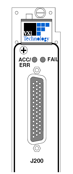
They are used to convey the following information visually to the user:
ACC/ERR – In normal use, this LED will remain off. This LED will glow constant red when a software error has occurred on the instrument. It will continue to glow red until all software errors have been cleared from the device’s error buffer.
FAIL – This light will remain green when the card is performing as expected from a hardware standpoint. Should a hardware failure occur, this light will turn red, and remain red. During initial power up, this LED will glow red until all system self tests have completed, at which point it will immediately turn green. At this point, the card is ready for regular use. -
What is a LAN Event?
LXI Instruments (with IEEE-1588 extension capability) with synchronized clock, share a common notion of time. LAN events are the capability of LXI instruments to communicate in detail the occurrence of pre-defined events in real time, and independent of a host PC
Part of the LXI specification is intended to standardize on how instruments will transmit packets of data over Ethernet intended to communicate real-time status of system level testing between devices.
In legacy test platforms, device to device communication has been limited to electrical hardware triggers. Using Ethernet as a measurement standard opens the door to expand on this concept. Not only can a device be notified that an event has occurred, but specific details about that event can also be transmitted. Furthermore, APIs included in the IVI Sync instrument driver class provide a programmatic interface for interpreting this information so that application SW can act appropriately based on the content of the LAN event. VTI Instruments delivers full compliance with all of their LXI products. -
What is a Reed Relay and what are Their Advantages in Signal Switching?
Reed relays can again be divided into Dry reed relays and Mercury wetted reed relays. Below diagram explains the general construction of a typical Reed relay.
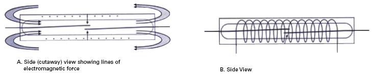
Dry Reed Relays
Contacts are made from ferromagnetic material (reeds). These contacts are encapsulated in glass. An energizing coil is wrapped around the glass and an EMF brings the two reeds together, closing the contacts.
Main Advantages
Hermetically sealed, reduces oxidation build-up
High Isolation (about 1014 Ω)
Main Disadvantages
EMFs effect adjacent relays – requires shielding of relays in high-density applications.
Inconsistent contact resistances.
Mercury Wetted Reed Relays
Similar in construction and operation to dry reed relays except that a small amount of mercury is added inside the glass tube to provide more consistent contact resistances.
Main Advantages
More power handling than a dry reed
Consistent and low contact resistances
Main Disadvantages
Position sensitive
Mercury is a sensitive material
Expensive relays
-
What is Crosstalk with Respect to Signal Switching?
Switches are designed to distribute a signal. However, in doing so, they will distort the signal to some extent. This distortion should be well defined and quantified in the switch specification. This information allows users to accurately choose a switch that is appropriate given the needs of their application.
Crosstalk is used to express the stay capacitance between adjacent channels on a switch card and is specified in dB. The greater this number, the better. The crosstalk specification is important to consider since it determines the amount of noise that is induced to the signal switched from an adjacent channel.
-
What is Normal Mode Noise?
Normal mode noise can occur as a result of common mode, electrostatic, or electromagnetic noise finding its way to the signal. In most cases, the noise is related to ac power lines. If so, it appears as a 50 Hz or 60 Hz sine wave added to the dc voltage that we want to measure.
A filter can be used to reduce 50 Hz or 60 Hz noise, but the slow response of the filter will slow down the measurements speed. Filters also inject some errors of their own.
TIP: The best way to eliminate power line noise is with an integrating voltmeter. The noise signal is integrated out with only minimal loss of speed. -
What is Path Level Programming?
Normal mode noise can occur as a result of common mode, electrostatic, or electromagnetic noise finding its way to the signal. In most cases, the noise is related to ac power lines. If so, it appears as a 50 Hz or 60 Hz sine wave added to the dc voltage that we want to measure.
A filter can be used to reduce 50 Hz or 60 Hz noise, but the slow response of the filter will slow down the measurements speed. Filters also inject some errors of their own.
TIP: The best way to eliminate power line noise is with an integrating voltmeter. The noise signal is integrated out with only minimal loss of speed.

In this example, a user would only have to use a connect() or disconnect() API to control the path between “IN 1” and “Out 1”. The IviSwtch driver is responsible for managing all the algorithms necessary to be intelligent about which specific relays need to be closed. Furthermore, the driver takes care of the communication to the hardware. In large switching systems, this saves the user the burden managing this in their software.
All VXI, LXI and PXIe switching solutions provided by VTI Instruments are fully compliant with the IVISwitch specification. -
What is Peer to Peer Communication?
Peer to peer communication is the communication between two networked devices, independent of any host PC or controller
Part of the LXI specification is intended to standardize on how instrumentation that uses Ethernet as the primary interface will use this technology to improve test efficiency by removing the need for a host controller under particular circumstances.
The EX10XXA family of products exemplifies how this technology can be taken advantage of. This product has been designed to simplify the process of performing a factory calibration. The means by which this is accomplished is primarily peer to peer communication
On the rear panel, the device is outfitted with a banana jack that is solely used in the calibration process. By hooking up the EX10XXA to a network with a standard DMM (Agilent 34410 for example) and connecting the DMM input to the calibration banana jacks, all the user needs to do is start the calibration process via a standard web browser. At that point, the EX10XXA takes advantage of peer to peer communication to communicate with the DMM and measure all of its internal reference voltages. The process from beginning to end is turn-key and requires no interaction from the host PC beyond initiation. The two devices utilize the network, and peer to peer communication to communicate with one another. -
What is Register Based I/O?
In general with respect to VXI based hardware, there are two industry wide standards for communicating to hardware. Message based and register based input and output. Instruments can utilize one or both protocols.
Register based I/O is communication to hardware using direct register access to perform writes and reads. The SMIP platform is VTI Instrument’s family of VXI based switching products which uses register based I/O to control the state of switches. In the simplest terms, users can write direct to registers in the VXI address space to control large groups of relays with one transaction. For example, writing or reading to a 16 bit register accomplishes commanding or querying the state of 16 individual relays with one hardware communication.
In general, the advantage of register based I/O is reduced test times due to significant reductions in communication transactions. Specifically, significant amounts of functionality can be executed with single hardware transactions. However, this increased efficiency introduces burden on the user in terms of software development and the time it takes to thoroughly understand a particular instrument’s register structure and operation. More specifically, the user interface is presented at a lower level requiring some up front software development to create a more intuitive user interface.
VISA is used industry wide as the standard software interface for sending both register based and message based commands to VXI instrumentation. -
What is the Maximum Switching Power Specification?
Maximum switching power is the upper limit of power which can be switched by a relay’s contacts without causing damage to the relay. Care should be taken not to exceed this value in signal switching applications.
It is also important to consider maximum switching current and voltage values in combination with maximum switching power since power can be expressed as a function of voltage and current. A common mistake is to assume that the maximum power specification can be derived directly from the maximum current and voltage specifications, and this is not always the case. -
When Should I Use a Latching vs. Non-Latching Relay?
Introduction: A definition of latching relays and non-latching relays as well as applications in which each type of relay is appropriate
Latching and non-latching describe the mechanism used to actuate/de-actuate electromechanical coils. To change the state of a latching relay (open/closed), a short pulse is sent to the set or reset lines on the relay. For non-latching relays, a constant source is required to maintain the 'on' position. Removing power from a non-latching relay (also referred to as failsafe relays) will return the contacts to their 'normal' or power-on state. Removing power from a latching relay will not affect the present state of the contacts (i.e., the contacts maintain their position at the time that power is removed).
Latching relays should be used when an application requires one or more of the following:
- The last state of the relay prior to power removal must be maintained.
- Thermal stability through power management. Because latching relays are pulsed to activate, there is minimal quiescent current draw while measurements are being made. Non-latching relays require constant current, and will radiate heat that may affect critical measurements.
- Better repeatability. Latching relays generally ensure more repeatable contact closures with regards to insertion loss over the life of the relay. Variations in insertion loss from closure to closure can affect critical measurements.
Non-latching relays should be used when an application requires one or more of the following:
- Cost is a factor. In general, latching relays will be less expensive than their latching equivalents.
- Relays need to be set to their normal position when power is removed. In normal operation, power removal is planned and handled elegantly. However, when power loss is not planned, it may be desirable, considering safety, to force the configuration of the box into it's normal/power-on state.
-
When Should I Use a Solid State Switch?
In a solid state relay an opto-isolator is typically used to control FETs, SCRs or TRIAC types of solid state devices.
Main Advantages
Offers long mean time between failures (MTBFs)
Very fast switching times (typically in microseconds)
Allows for high density signal switching
Main Disadvantages
Degrades signal integrity
Typically not bi-directional
Not useful for high voltage swings -
Why the Frequency Domain?
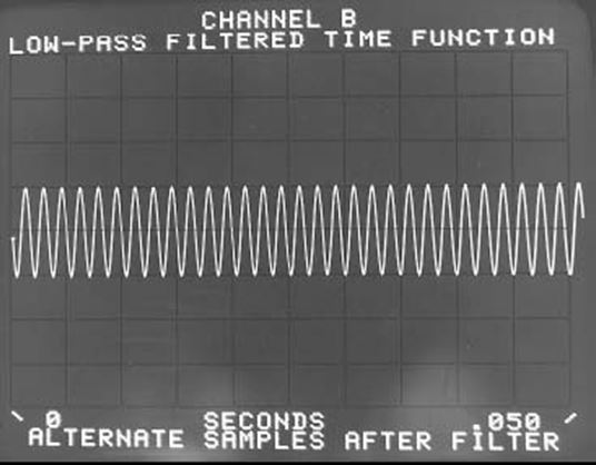
Suppose we wish to do modal analysis on solid rocket motor during a test fire. Or we might be trying to detect the particular audible frequencies in a noisy test chamber. In each case, we are trying to detect a small periodic wave in the presence of large signals. In the picture below we see a time domain waveform which seems to be single sine wave.
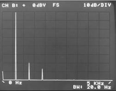
The following image shows in the frequency domain that the same signal is composed of a large sine wave and significant other sine wave components (distortion components). When these components are separated in the frequency domain, the small components are easy to see because they are not masked by larger ones. The frequency domain’s usefulness is not restricted to electronics or mechanics. All fields of science and engineering have measurements like these where large signals mask others in the time domain. The frequency domain provides a useful tool in analyzing these small but important effects.
-
Can the EMX-2500 be used in PXI/PXIe chassis from other manufacturers?
The EMX-2500 can be used in PXI/PXIe chassis from other manufacturers but certain features such as the IEEE-1588 works with VTI's PXIe chassis only. -
How Do I Control EX1000 Series Instruments in Linux?
VTI provides interface for the user to control EX1000 series instruments in Linux. Please download the attached file for the EX1000 Linux interface.
Linux-tools -
How To Control EX1000 Series Instruments in C#?
Following the instructions below, you can easily control any EX1000 series instrument in C#
- Go to http://www.ivifoundation.org to download the latest version of IVI Shared Components Package.
- Go to https://www.vtiinstruments.com to download the latest version of EX10xxA IVI COM driver.
- Install both the IVI Shared Components Package and EX10xxA IVI COM driver.
- Open Visual Studio and create a new Console Application project.
- Right click on "Reference" in "Solution Explorer" and click on "Add Reference".
- Add the IVI VTEX10xxA Type Library into the project.
You are now ready to begin to code to control any EX10xxA instrument.
Please refer to the VTEX10xxA.chm file found in the EX10xxA IVI COM driver folder for more information.
A simple example program can also be downloaded from the attachment in this FAQ.
EX10xxA_CSharp -
How To Control EX1000 Series Instruments in VB.NET?
Following the instructions below, you can easily control any EX1000 series instrument in VT.NET
- Go to http://www.ivifoundation.org to download the latest version of IVI Shared Components Package.
- Go to http://www.vtiinstruments.com to download the latest version of EX10xxA IVI COM driver.
- Install both the IVI Shared Components Package and EX10xxA IVI COM driver.
- Open Visual Studio and create a new Console Application project.
- Right click on the project in "Solution Explorer" and click on "Add Reference".
- Add the IVI VTEX10xxA Type Libary into the project.
You are now ready to begin to code to control any EX10xxA instrument.
Please refer to the VTEX10xxA.chm file found in the EX10xxA IVI COM driver folder for more information.
A simple example program can also be downloaded from the attachment in this FAQ.
EX10xxA_VB -
How To turn EX10xxA Calibration report into CSV Format File?
Install the EX10xxA IVI COM driver or Plug&Play driver.
Initialize the instrument and call the "vtex10xxA_get_calibration_file" function to download the calibration file into the host computer.
Install the attached software application and following the instrucations below
- Open the software
- Click "Browse"
- Choose the EX10xxA calibration XML format file you would like to convert
- Click "Process"
- Choose a designation that the CSV format file will save into
Once it is done, you can open up the CSV format file and check out the calibration detail.
EX1000CalibrationConverter -
What are the advantages of using an IVI Driver?
The VXIplug&play drivers did not provide a common programming interface, which means each time you buy a new instrument you need to spend a lot of time learning each individual driver. In order to reduce the cost of program development and its associated maintenance, and to simplify the interchangeability, in 1998 a group of End Users, Instrument Vendors, Software Vendors, System Suppliers and System Integrators joined together and formed a consortium called the "Interchangeable Virtual Instruments (IVI) Foundation". The IVI Foundation defines the IVI specifications for programming test instruments.
The advantages of using IVI Driver are:
Consistency – IVI drivers all follow a common model of how to control the instrument. That saves you time when you need to use a new instrument.
Ease of use – IVI drivers feature enhanced ease of use in popular Application Development Environments (ADEs). The APIs provide fast, intuitive access to functions. IVI drivers use technology that naturally integrates in many different software environments.
Quality – IVI drivers focus on common commands, desirable options, and rigorous testing to ensure driver quality.
Simulation – IVI drivers allow code development and testing even when an instrument is unavailable. That reduces the need for scarce hardware resources and simplifies test of measurement applications. The example programs in this document use this feature.
Range checking – IVI drivers ensure the parameters you use are within appropriate ranges for an instrument.
State caching – IVI drivers keep track of an instrument’s status so that I/O is only performed when necessary, preventing redundant configuration commands from being sent. This can significantly improve test system performance.
Interchangeability – IVI drivers enable exchange of instruments with minimal code changes, reducing the time and effort needed to integrate measurement devices into new or existing systems. The IVI class specifications provide syntactic interchangeability but may not provide behavioral interchangeability. In other words, the program may run on two different instruments but the results may not be the same due to differences in the way the instrument itself functions.
Thus IVI specifications enable drivers to be of complete, usable and high standard quality.
Reference: IVI Getting Started Guide. -
What Do I Do if My EX1200 System Is Locked After a Recovery from a Connection Lost?
In case that the EX1200 system is locked after a recovery from a connection lost, the software you are using to communicate with the hardware might not be able to reconnect to the hardware within the next couple minutes. A hardware reset can be performed to allow the software to reconnect to the hardware again immediately without waiting.
Attached file is a simple program that performs hardware reset on any EX1200 system.
EX1200_Hardware_Reset_CPP -
What is DHCP?
DHCP – Dynamic host configuration protocol is general network protocol used across many industries to manage IP addresses on complex networks. In the simplest terms, it is a method by which a look up table is used to map a piece of network hardware’s MAC address to a unique IP address. This table is usually stored and managed on a DHCP server. Network administrators typically use this protocol in combination with standard IT toolsets to manage and organize all the networked HW within their organization.
With respect to LXI, DHCP is one of the required protocols an LXI instrument must respond to when plugged into a network that has a DHCP server on it. The primary benefit of this for LXI users is their instrumentation will automatically behave with other office hardware when used on a corporate network. Furthermore, instruments will usually always receive the same IP address since it is determined by the device’s permanent MAC address. -
What is Electromagnetic Noise?
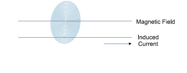
A magnetic field that is changing will cause a current to flow in a conductor running through it. Conversely, a current flowing in a wire has a magnetic field associated with it. Therefore, one wire with a current flowing in it can cause a current to flow in another wire (inductive coupling)
TIP: Whenever possible, keep signal lines away from noise sources (i.e. other wires carrying large currents).
TIP: To eliminate interference currents, twist your wire pairs so that the current induced in one loop cancels out the current induced in an adjacent loop. This is a simple, no-cost way to reduce electromagnetic noise.
-
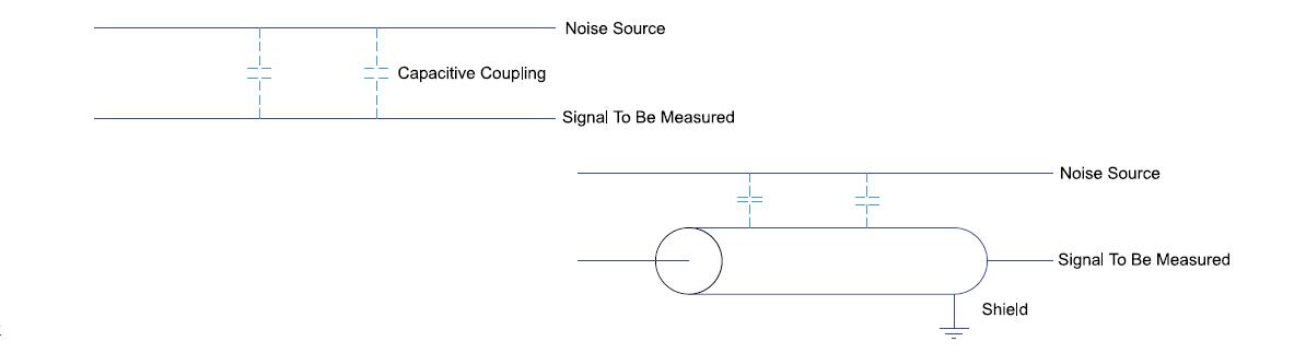
What is Electrostatic NoiseA voltage on one wire can be capacitively coupled to an adjacent parallel wire as a result of an electric field. The signals from power lines are the most common noise sources.
TIP: Whenever possible, run signal lines away from noise sources (i.e., other unshielded wires carrying large voltages).
TIP: Use shielded wire to reduce the effects of capacitive coupling. The voltage will couple to the shield and not to the protected wire.
TIP: Ground one end of the shield to keep voltages built-up on the shield from capacitively coupling to the protected wire. NEVER ground both ends of the shield!
TIP: For the best possible temperature measurements, use a shielded thermocouple and a guarded voltmeter. Tie the shield to the thermocouple junction and to Guard. Do NOT ground the shield.
TIP: If not using a three-wire (shielded) thermocouple, tie Guard to Low. Leaving Guard unattached will not make use of its ability to reduce noise. -
What is End to End Self Calibration?
Introduction: A definition of self calibration followed by a discussion of the benefits to measurement integrity
Accurate test and measurement applications are a key component in ensuring that products and systems that we depend upon are reliable and safe. Poor measurement quality can be devastating, resulting in schedule setbacks, substantial monetary losses, and endangerment of human safety. It is critical that test engineers can rely on their instruments and the integrity of the data they produce.
Measurement integrity or confidence has traditionally been achieved through annual instrument calibration using traceable verification standards.
One risk worthy of considering is whether or not the before mentioned annual calibration is still current and valid before any given measurement. In some cases significant thermal drifts or degradation of particular components in the analog circuitry can compromise the integrity of a measurement.
Confidence in Data with Routine Self-Calibration
When ATE instruments are designed with on-board precision voltage references, it can be used to guarantee reliable and accurate measurements regardless of the time or ambient temperature of the last factory calibration. Before any measurement is initiated, users can initiate a self-calibration sequence that routes the precision source back through the input signal paths of the instrument. This process makes minor gain and offset adjustments to the signal path. Whenever the device undergoes any changes in its surrounding thermal environment, this process can be executed to mitigate the effects of the thermal drift.
The following table quantifies the benefits of having a routine self-calibration procedure built in to your instrumentation. This data is from the example system, the EX1048A instrument configured for Type-E thermocouple measurements and connected to a precision thermocouple simulator.
The first table shows the source value and five readings from the instrument.
Accuracy Analysis of EX1048A Before Self-Calibration
Precision Source -100° C 0° C 100° C 300° C 500° C 700° C 900° C EX1048A Measurement 1 -100.60° C -0.50° C 99.58° C 299.62° C 499.41° C 699.33° C 899.25° C EX1048A Measurement 2 -100.61° C -0.51° C 99.59° C 299.63° C 499.40° C 699.34° C 899.26° C EX1048A Measurement 3 -100.62° C -0.52° C 99.57° C 299.59° C 499.42° C 699.35° C 899.25° C EX1048A Measurement 4 -100.61° C -0.50° C 99.58° C 299.60° C 499.41° C 699.33° C 899.24° C EX1048A Measurement 5 -100.60° C -0.51° C 99.58° C 299.61° C 499.41° C 699.34° C 899.24° C
If you compare the first table with the following table, which shows the same readings after the unit has been self-calibrated, there is an improvement in accuracy of approximately .05%, clearly demonstrating significant improvement in the data quality after the self-calibration is performed. The calibration was performed from the front of the instrument with out connecting any additional hardware. Simply pushing a button and launching an automated routine ensures quality measurements.
Accuracy Analysis of EX1048A After Self-Calibration
Precision Source -100° C 0° C 100° C 300° C 500° C 700° C 900° C EX1048A Measurement 1 -100.17° C -0.17° C 99.82° C 299.84° C 499.83° C 699.84° C 899.80° C EX1048A Measurement 2 -100.16° C -0.14° C 99.84° C 299.83° C 499.84° C 699.82° C 899.81° C EX1048A Measurement 3 -100.17° C -0.15° C 99.83° C 299.83° C 499.84° C 699.83° C 899.80° C EX1048A Measurement 4 -100.18° C -0.15° C 99.84° C 299.83° C 499.83° C 699.84° C 899.84° C EX1048A Measurement 5 -100.17° C -0.17° C 99.85° C 299.82° C 499.83° C 699.84° C 899.80° C
VTI Instruments, Inc. has taken measures to ensure these benefits and advantages in calibration and associated measurement integrity are an integral part of all of its next generation products. These exciting features are included in VTI Instruments, Inc. EX10XXA precision thermocouple/Voltage device and the EX1629 static strain measurement device.
-
What is IEEE 1588?IEEE 1588, also known as precision time protocol is a world wide standard for synchronizing clocks over a network.
Part of the LXI specification is intended to standardize on how instrumentation that uses Ethernet as the primary interface will use this technology to synchronize over the network. In the simplest terms, the following outlines the process:
At power up all LXI devices begin intercommunication
Together, they determine which device has the most accurate and precise clock source
That device is deemed the master of the system with respect to time.
Periodically, the master imposes its notion of time onto all of its slaves and corrects for errors.
Using this technology, distributed instruments on a network can be synchronized with similar accuracies seen in traditional backplane architectures such as VXI and PXIe. What LXI compliance effectively does is distribute the backplane over Ethernet. The result is the same performance without the constraints imposed by a physical rigid backplane. Now synchronized instruments can be placed virtually anywhere with respect to each other. -
What is Instrument Locking w/LXI Devices?
Different from legacy test and measurement platforms, LXI provides for the capability to distribute instrumentation. When instruments are distributed over a network, it is not obvious, which, or how many computers might be connected to the network, and attempting to access the same LXI hardware. It is for this reason that instrument locking is a useful capability.
If locking capabilities are to be used, it makes sense to provide users with the ability to lock instruments, to unlock instruments, and to break a lock. Once an instrument is locked, it can only be unlocked by the client who locked it. Users also have the ability break a lock created by another client. However, they are given an explicit warning that they are breaking another client’s lock before they can execute the break.
Locking functionality can be executed through two different interfaces. Users can use the embedded web interface to lock/unlock their LXI device using a standard web browser, or users can access the locking functionality through APIs delivered in the IVI instrument driver. -
What is IVI?
The Interchangeable Virtual Instruments standard (IVI) is a relatively new specification that has been introduced primarily as a means of isolating the application code from the specific instrumentation within a system. IVI drivers are divided into various classes based on instrument functionality (e.g. IviScope) and builds on the VXIplug&play specification by providing features, such as state caching, that improve system performance. IVI drivers are intended to allow an ATE developer to replace one vendor’s instrument with one from another vendor within the same class without any modification to application code.
An instrument class accounts for the most common features and functionality within that class. For example, the IviScope class defines channel counts, possible trigger sources, and sample record lengths in addition to other common scope functions. Digitizers could also fall under the realm of this class as it is defined. It is important to note that IVI drivers can be provided with either a C or COM application interface which are optimized for specific development environments and it is up to the vendor whether they want to support one or both of the interfaces.
Part of the LXI standard is that all LXI compliant devices deliver an IVI driver. While the driver does not have to be instrument class compliant, it does have to provide to the common core capabilities of IVI. For example, an LXI compliant DMM does not have to deliver an IVI driver that is IviDMM compliant, but it must deliver a driver that complies with the basic IVI requirements regardless of instrument class.
As of this writing, instrument class definitions continue to evolve. Some of the most common classes have been defined. For the latest information regarding IVI, refer to our industry specifications web page. -
What is VSWR with Respect to Signal Switching?
VSWR (voltage standing wave ration) is a signal switch specification that is usually only important in high frequency, microwave applications.
At high frequencies, resonance is generated from the interference between the input signal and the corresponding reflected signal. VSWR is specified as the ratio of the maximum value to the minimum value of the waveform. In simpler terms, the smaller the VSWR specification, the less effect the reflected signal will have on the signal the switch is intended to transmit -
What is VXI Plug&Play?
VXI Plug&Play is a well defined standard for developing instrument drivers used to control VXI hardware. The objective of the standard is to deliver to users a familiar and easy to use driver with all VXI equipment, regardless of vendor.
The VXI community has worked hard at developing a set of system-level standards for instrument drivers that are classified as VXI plug&play. VXI plug&play drivers offer interoperability of multivendor software and hardware components and increase productivity by delivering an easy-to-use interface that makes the low level I/O communications and hardware drivers transparent to the programmer.
The foundation of a VXI plug&play driver is VISA (Virtual Instrument Software Architecture). VISA defines a protocol for I/O communication to VXIbus devices that is supported by multiple vendors. VISA supports non-VXI instrumentation platforms as well and while it is a defined set of standards, the version of VISA will be dependent on the instrument control interface. For example, if there is an Agilent IEEE-488 controller card interfacing to a Tektronix scope, Agilent-VISA would need to be installed on the PC. Conversely, if a National Instruments VXI-MXI2 card is interfacing to a VTI Instruments VM2616 digitizer, NI-VISA would be installed. Each version of VISA utilizes the defined set of standards which brings true interoperability. In other words, a VXI plug&play driver will work with either an Agilent or NI VISA layer. VTI Instruments is committed to supplying products that will work with Agilent or NI’s VISA whenever possible. -
What Switch Card Type Should I Use For My Application?
Different applications often demand specific relays types. Typically, what differentiates a relay are its specifications. In general, these applications can be broken down into the following categories:
High power switching applications call for switch cards that use high power electro-mechanical relays. These relays can handle signals in excess of 2A. VTI Instruments has several high power switch configurations to suit various platforms; in VXI, the SMP2xxx series; in LXI the EX1200-2xxx family; and in PXI, the SMX-2xxx family.
General purpose switch cards are designed for low-level and low frequency applications (less than 2A and typically less than 20MHz). VTI Instruments has several general purpose switch configurations to suit various platforms; in VXI, the SMP3xxx series, SMP4xxx series, and SMP5xxx series; in LXI, the EX1200-3xxx series, EX1200-4xxx series, and the EX1200-5xxx series; in PXI, the SMX-3xxx series, SMX-4xxx series, and SMX-5xxx series.
RF switch cards have controlled impedance (50 or 75 Ohms). These modules are designed to handle RF signals under 3GHz. VTI Instruments has several RF switch cards; the SMP6xxx series in VXI form factor; EX1200-6xxx series in an LXI configuration; and SMX-6xxx series in PXI form factor.
Microwave switch cards designed for switching frequencies between 1 GHz through 40 GHz. The SMP7000 series or EX7000 series or SMX-7000 series can accommodate this application.
Optical switching cards designed to switch fiber optic signals – The SMP8xxx series of products. -
What Switch Card Type Should I Use For My Application?
In any VXI system, it is necessary to have a slot-0 interface to serve as the hardware communication layer between the host PC and the VXI bus. The following is a list of options when choosing a slot 0 controller:
1. IEEE-488.2 (GPIB) to VXIbus. With this approach a GPIB interface card is housed in the external computer, and is connected to a GPIB/VXI Slot 0 in the VXIbus mainframe. This is an 8-bit parallel protocol, therefore, it’s typically the slowest way of communicating between a remote host and the VXI mainframe (about 1 MB/s).
2. MXI-2 Interfaces. With this approach a MXI-2 interface card is housed in the external computer, and is connected to a MXI-2 Slot 0 in the VXIbus mainframe. This approach extends the VXIbus backplane to the external computer. It is a 32-bit protocol, and offers some of the fastest transfer rates between a remote PC and the mainframe at around 25 MB/s.
3. IEEE-1394 (FireWire) As with the previous two interfaces, this requires a remote PC. An IEEE-1394 Slot 0 interface card in the VXI mainframe connects to the 1394 port on the external computer. This is a serial protocol that operates at about 400 Mb/s. 15 MB/s Transfer rates between the remote and the mainframe can be achieved, though because of protocol overhead, maximum system speed is seen when transferring large blocks of data as opposed to sending discrete commands.
4. Embedded Controllers. This approach embeds the controller within the VXIbus mainframe (typically in Slot 0). Embedded controllers can be Pentium computers, Motorola 68XXX based controllers or other platforms. The hardware interface to the VXIbus backplane is built into the embedded controller with this approach, similar to a parallel port.
5. VXI/LXI Bridge. The EX2500A is a slot zero controller that serves as both a VXI interface and an LXI bridge. Being fully LXI Class A compliant, it allows users to send trigger events over Ethernet, or over the well defined hardware trigger interfaces in both the VXI and LXI application space. Since it is Ethernet based, it provides the capability to distribute VXI instrumentation large distances away from the host PC. Much further than any legacy interfaces to date. In high speed data acquisition applications where large block transfers are used, it typically can transfer data at faster rates than legacy VXI interfaces. -
Additional LabVIEW examples for VTEXDsa
Here are some LabVIEW examples for VTEXDsa at “VTEXDsaExamplesLabVIEW.zip”. These vi’s should get placed in the “<LabVIEW>\instr.lib\VTI Instruments VTEXDsa\Examples” folder as additions to our LabVIEW support, and then added to the example folder of the “VTI Instruments VTEXDsa” project.
There are five VI’s that make three examples. Two VI’s are general utility functions used by two of the examples. These are:
• GetEnabledChannels.vi – This is mostly for the purpose of getting how many channels in the system are enabled. It also returns that list.
• ParseData.vi – This will take a single dimensioned array of data as it gets returned by our driver, and parses it into a two dimensioned array of scans by channels given record count, record size, and channel count associated with the input data array.
Two examples that both use the above:
• DataAcq2.vi – More features added to the ‘DataAcq.vi’ example. It uses the Platform interface functions for getting system information, and parses out channel data instead of getting all channels and records as one large array.
• StreamingExp.vi – For testing the new memory streaming engine of VTEXDsa v1.6.7 and testing of high channel count systems for high throughput. It allows easy switching between the ReadMeasurement() and MemoryRead() methods of data retrieval for comparison. It’ll extract/graph/strip chart a given range of channels on the fly, and implements a few other tools for bench marking performance. (e.g. how long did it take to configure 100 channels, how long did it take to get my first data record, how busy is it getting data vs waiting for data, etc.) Also supports syncing multiple chassis.
Stand-alone example:
• SelfCal.vi – Does a Self-Cal indicating status as it does it, puts out reports when finished.
Additional LabVIEW examples for VTEXDsa -
EX1200-3048 Scanning Application C# Code
Using EX1200-3048 as a Scanner with an External Voltage Measure Instrument, example C# Code.
062714_AppNote_UsingTheEX1200_3048
EX1200_3048_scanning -
EX1200-3608 DMM Measurement Labview Example Code